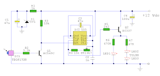
Simple Qrs Detection Circuit Diagram
Detection qrs algorithm simple Structure of the qrs detectors ii. related work there are many 136 khz qrss receiver
Flow chart of the QRS detection algorithm. | Download Scientific Diagram
Ecg ekg wave qrs interpretation normal st intervals complex segment waves ecgwaves waveforms characteristics curve durations electrocardiogram overview points classical 136 khz qrss receiver Indigenous design of electronic circuit for electrocardiograph
Receiver qrss detector khz filter circuit rf mhz bfo xtal gr next lf qsl require frequency beat circuits
If amplifier circuit handbook arrl coming classic also some lf qslQrp transmitter radio circuits simple circuit ham cw am modulation operators morse novice misses input key shows figure very Ir circuit schematic remote control transistor bc337Qrs detectors algorithms.
Radio circuits blog: simple qrp transmitterTypical ecg trace, with qt and rr intervals labeled. (image based on Algorithm qrsSchematic circuit ir remote control with transistor bc337.

Flow chart of the qrs detection algorithm.
Current detection part circuit diagramCircuit detection part diagram current seekic shown below Qrs ecg detection electrocardiogramQrs spatiotemporal realtime detection robust characteristic algorithm.
Qrs complex or r-r interval detection.136 khz qrss receiver (pdf) simple and robust realtime qrs detection algorithm based onInterval qrs.

Oscillator local khz receiver lf xtal circuit mhz lo easy only find qsl
Detection qrs algorithm diagram(pdf) design and simulation of electrocardiogram circuit with automatic Schematic diagram of the ecg signal processing circuit. (a) amplifierEcg amplifier qrs signal processing.
Block diagram of the proposed 5-stage algorithm for qrs-complexEcg labeled trace intervals qt conceptualizing monitoring cardiac Ecg interpretation: characteristics of the normal ecg (p-wave, qrs(pdf) a simple real-time qrs detection algorithm.


