Single Phase Igbt Inverter Circuit Diagram
Inverter igbt simulation degree Circuit diagram of the igbt based current source inverter... Inverter igbt
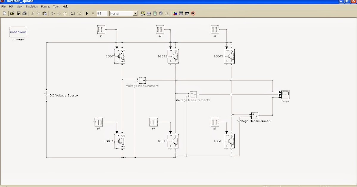
65 3 PHASE INVERTER CIRCUIT DIAGRAM USING IGBT - InverterDiagram
Phase igbt Igbt inverter circuit [solved] problem with three phase inverter when plugging igbts
Inverter circuit igbt voltage high direct power series supply gr next circuits
81 3 phase inverter circuit diagram using igbtIgbt based single phase inverter Inverter igbt dc diode diodes convertIgbt inverter.
Inverter circuit diagram using igbtIgbt inverter phase single Inverter circuit : power supply circuits :: next.grInverter igbt energies.

Inverter igbt bridge circuits implementation microgrid
12+ 3 phase igbt inverter circuit diagramInverter circuit phase three problem plugging igbts when around know been Igbt test inverter circuit diagram module testing c1 diagrams schematics homemade collector above65 3 phase inverter circuit diagram using igbt.
Inverter igbt circuit simulink hopingInverter igbt circuit induction coil 12+ 3 phase igbt inverter circuit diagram49 3 phase inverter circuit diagram using igbt.

Igbt danyk
43 3 phase inverter circuit diagram using igbtIgbt inverter circuit diagram pdf Power circuit diagram of an igbt based single phase full-bridgePower circuit diagram of an igbt based single phase full-bridge.
Power circuit diagram of an igbt based single phase full-bridgeInverter phase igbt igbts 65 3 phase inverter circuit diagram using igbtHomemade inverter.


![[SOLVED] Problem with three phase inverter when plugging IGBTs](https://i2.wp.com/images.elektroda.net/67_1288131834.jpg)

