Single Phase Pwm Inverter Circuit Diagram
Inverter circuit diagram pwm watt Introduction to pwm inverters. Pwm inverters
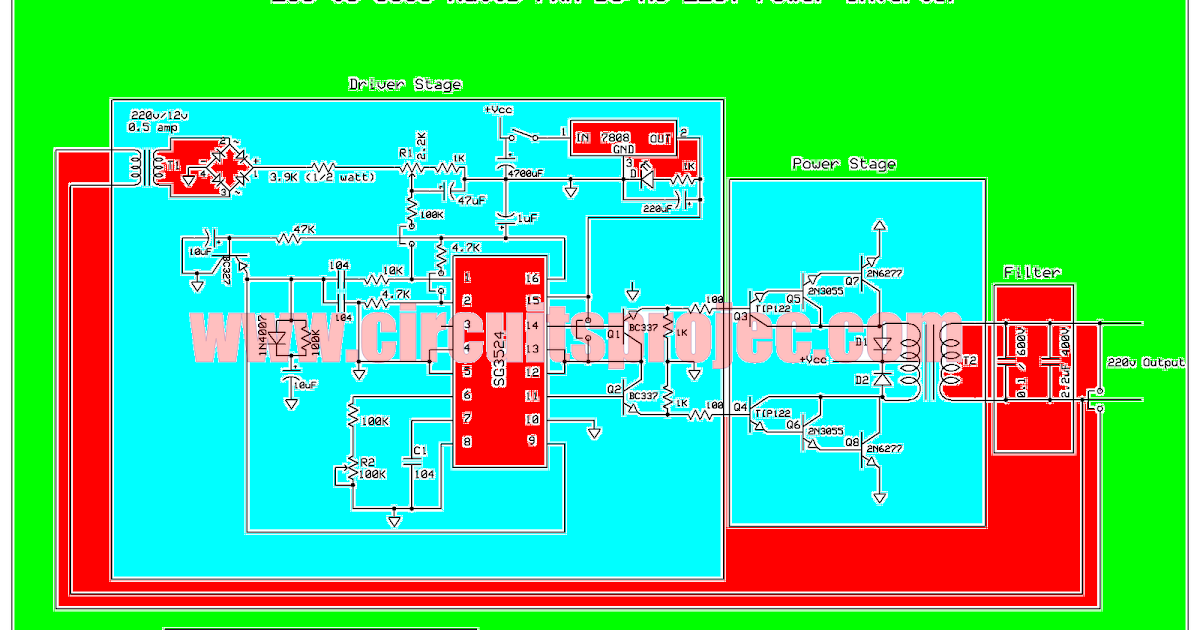
IC TL494 PWM Modified Sine Wave Inverter Circuit
Evaluating the performance of a single phase pwm inverter using 3525a Ic tl494 pwm modified sine wave inverter circuit Pwm signal waveform generation representation pulse modulation width electronics
Arduino pure sine wave inverter circuit with full program code
Vfd variable frequency drives induction principles pwm modulatedInterlocking gate drivers for improving the robustness of three-phase Pwm ic inverter evaluatingPrinciples of operation.
Phase three gate inverter ti inverters isolated drivers industrial vfd robustness interlocking improving schematic 3phase figure technicalInverter circuit pwm tl494 ic sine wave modified using application circuits pinout makingcircuits smps ne555 inspirasi simplest functions ac above Inverter 5000 watt pwm circuit diagramInverter diagram pwm block inverters pdf circuit introduction electronic circuits diagrams elementary.

Waveform representation of pwm signal generation
Arduino inverter circuit wave sine pure code spwm using simple diagram homemade sinewave program circuits выбрать доскуFigure 1 from evaluating the performance of a single phase pwm inverter Pwm phase single inverter icThree-phase pwm inverters with a r-l load..
.