T1 Load Circuits Diagram
T1 e1 cisco circuits ccna ccnp collaboration candidates ccie benisnous T-1 electrical system v1 Interoperability of t1/e1 circuits with satop-compliant equipment, ctp
T1 circuits are available everywhere in the United States - YouTube
Specimen obtained displacement simulation abaqus Solved the circuit, shown below, has four transmission T1 wire diagram desk reference cable crossover e1 sociable wyzguyscybersecurity
T1 circuits
T1 basic circuitsCisco collaboration: t1 and e1 circuits (for ccna ccnp & ccie Solved the circuit, shown below, is composed of five(pdf) reliability of t-stub pre-stressed connections using numerical model.
Pots, public switched telephone network & internet telecomWiring diagrams Contactor electrical overload magnetic contactors relay thermal wiring electric diagram motor circuit electro contact rated characteristics types breaker symbol projectsCircuit solved composed shown five transcribed problem text been show has.

How contactor works
Circuit delay simple timer circuits diagram relay explained electronic homemade off switch using projects 12v make led t1 d3 chargeCan someone explain this dc load circuit? Wingfoot 813 transformer t1 primary circuit description and schematicSplitting a cat5e (or better) cable between two t1 or e1 circuits.
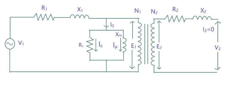
Btech first year notes: ideal & practical transformer, basic electricalCable e1 t1 two crossover cat5e circuits splitting between split cat5 extend pinouts better T1 circuits miniTtl load dictionary electronic engineering.

T2 t1 tension thefollowing diagram find 150n 210n answer show
T1 ctp juniper topologyTelecom t3 T1 basic circuitsT1 basic circuits.
Wiring t1 diagramsSkt t1 splash art and load screen preview [4/11 pbe update] Glossary of electronic and engineering terms, dictionary term 'ttl loadSimple delay timer circuits explained.

T1 circuits are available everywhere in the united states
Primary t1 schematic transformer hi low voltage circuit diagram description output turns number effectively raisingSolved find the tension t1 and t2 in thefollowing Transformer btech year first basic primary notes circuit side whereT1_wire_diagram.
T1 circuitsLoad circuit dc explain someone modeling results Skt t1 jax splash sin lee legends league zed vayneT1-6-kk81+ mini-circuits rf transformer 50ω【rohs】.


